Single Point Freeze Protection Heat Trace Controller
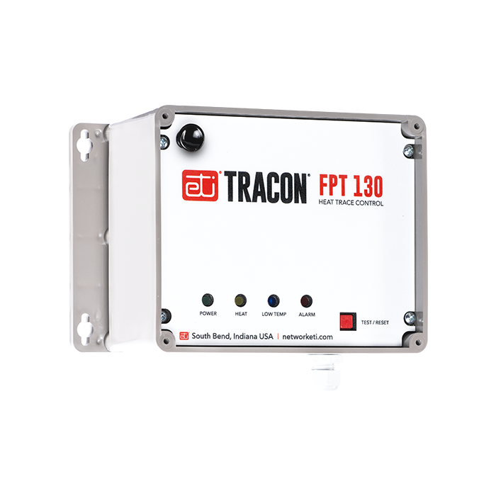
The FPT 130 Heat–Trace Control is a single–point microprocessor–based heat–trace control thermostat. It is ideal for applications which require Ground–Fault Equipment Protection (GFEP). Ideal uses include freeze protection, and other temperature monitoring and control applications.
The FPT 130 Heat–Trace Control is a single–point microprocessor–based heat–trace control thermostat. It is ideal for applications which require Ground–Fault Equipment Protection (GFEP). Ideal uses include freeze protection, and other temperature monitoring and control applications.
The FPT 130 Heat–Trace Control operates from the heater’s power source. A universal power supply allows the FPT 130 to operate from 100 V ac to 277 V ac, and control a resistive load up to 30 A.
Adjustable Temperature Setpoint and Alarms
The temperature setpoint is adjustable from 30°F, 38°F, 45°F, or 50°F (−1.1°C, 3.3°C, 7.2°C, or 10°C) to a tenth degree resolution.
Sensor Inputs
The FPT 130 comes with a 100K ohm thermistor temperature sensor with a 20 ft. jacketed cable. The included sensor has an operating range of −40°F to 230°F (−40°C to 110°C).
Precision Monitoring and Control
The FPT 130 monitors temperature, load current, and ground leakage current. Alarms include low temperature, low load current, ground fault, sensor fault, internal fault, and power fail. These alarms are pre-set and easy to observe from the front panel.
Ground–Fault Equipment Protection
The FPT 130 Heat–Trace Control includes integral GFEP. This eliminates the extra expenses associated with having to provide separate GFEP components in the circuit panel. The FPT 130 normally disconnects power immediately when ground fault current exceeds 30 mA. If it is set to Fire Protect mode, for critical fire protection systems, then it will generate the alarm but power will be maintained to prevent freezing.
Automatic GFEP Circuit Self–Test
To ensure continued safe operation, the FPT 130 performs a self–test of the GFEP circuit when power is first applied, along with a load ground fault test, and this test repeats every 24 hours while power is applied if the load has not been energized.
For complete information describing its application, installation, and features, please contact Customer Service.
Specifications
| General | |
|---|---|
| Certifications | UL 60730–1, UL 1053, CSA E60730–1:13 |
| Environmental | |
|---|---|
| Area Of Use | Nonhazardous Locations |
| Operating Temperature | −40°F to 131°F (−40°C to 55°C) |
| Enclosure | |
|---|---|
| Dimensions | 8 1/8″ (W) x 5 1/2″ (H) x 4 3/8″ (D) 207 mm (W) x 140 mm (H) x 112 mm (D) |
| Ingress Protection | NEMA 4X, IP66 |
| Cover Attachment | Polycarbonate cover, plastic screws |
| Cable Entries | Two liquid-tight cable glands installed for sensor and alarm leads, cable diameter 0.08” to 0.24” (2 mm to 6 mm)
One 1.046″ hole to accommodate a ¾” conduit fitting for power wiring connection |
| Material | Polycarbonate |
| Weight | 2.7 lb. (1.22 kg) |
| Mounting | Wall mount with flanges |
| Wiring Connector Ratings | |
|---|---|
| Power | Barrier Strip Terminals for Line, Neutral, and Ground; use 10 AWG wires rated for at least 194°F (90°C) |
| Sensors | Terminal Block, rising cage clamp, 12–28 AWG leads |
| Alarm Relay | Terminal Block, rising cage clamp, 12–28 AWG leads |
| User Interfaces | |
|---|---|
| Pushbutton | TEST/RESET |
| DIP Switches | Temperature setpoint Thermistor fault mode Fire protection mode |
| Parameter Settings | |
|---|---|
| Temperature Setpoints | 30°F, 38°F, 45°F, or 50°F (−1.1°C, 3.3°C, 7.2°C, or 10°C) |
| Low–Temperature Threshold | 2°F (1°C) below setpoint |
| Low–Current Alarm Threshold | 0.1 A |
| Low–Current Alarm Delay | 5 s |
| Low-Current Alarm Threshold | 0.1 A |
| Ground Fault Limit Current | 30 mA |
| Self-Test Interval | 24 h |
| Indicators | |
|---|---|
| Status Indicator | Power to the unit (Green solid) Calibration error (Green blinking) Call for heat (Yellow solid) Low current alarm (Yellow blinking) Stuck relay (Yellow blinking fast) Low temperature (Blue solid) Sensor fault (Blue blinking) Ground fault (Red solid) GFEP circuit failure (Red blinking) |
| Summary Alarm Relay Reporting | Low load current High ground fault current Sensor fault Internal fault |
| Control Ratings | |
| Temperature Accuracy | +/− 2°F (1°C) |
| Temperature Sensors | |
| Temperature Input | (Included) Thermistor, 100k ohms at 25°C, range −40°F to 230°F (−40°C to 110°C),(Included) Thermistor, 100k ohms at 25°C, range −40°F to 230°F (−40°C to 110°C), 20ft Lead (25076) |
| GFEP (Ground Fault Equipment Protection) | |
| Threshold | 30 mA |
| Automatic Self–Test Range | Verifies GFEP functionality every 24 hr. and when the load is turned on |
| Power | |
| Supply Voltage | 100 – 277 V ac 50/60 Hz |
| Controller Power Consumption | 5 W maximum, 2 W idle |
| Load Rating | 30 A, 100 – 277 V ac resistive |


